A precision holder designed to rotate the beak and surgical needle through a finger-driven rack and gear system, reducing wrist rotation while improving control in confined suturing spaces.
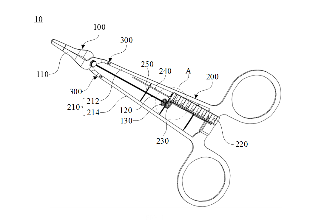
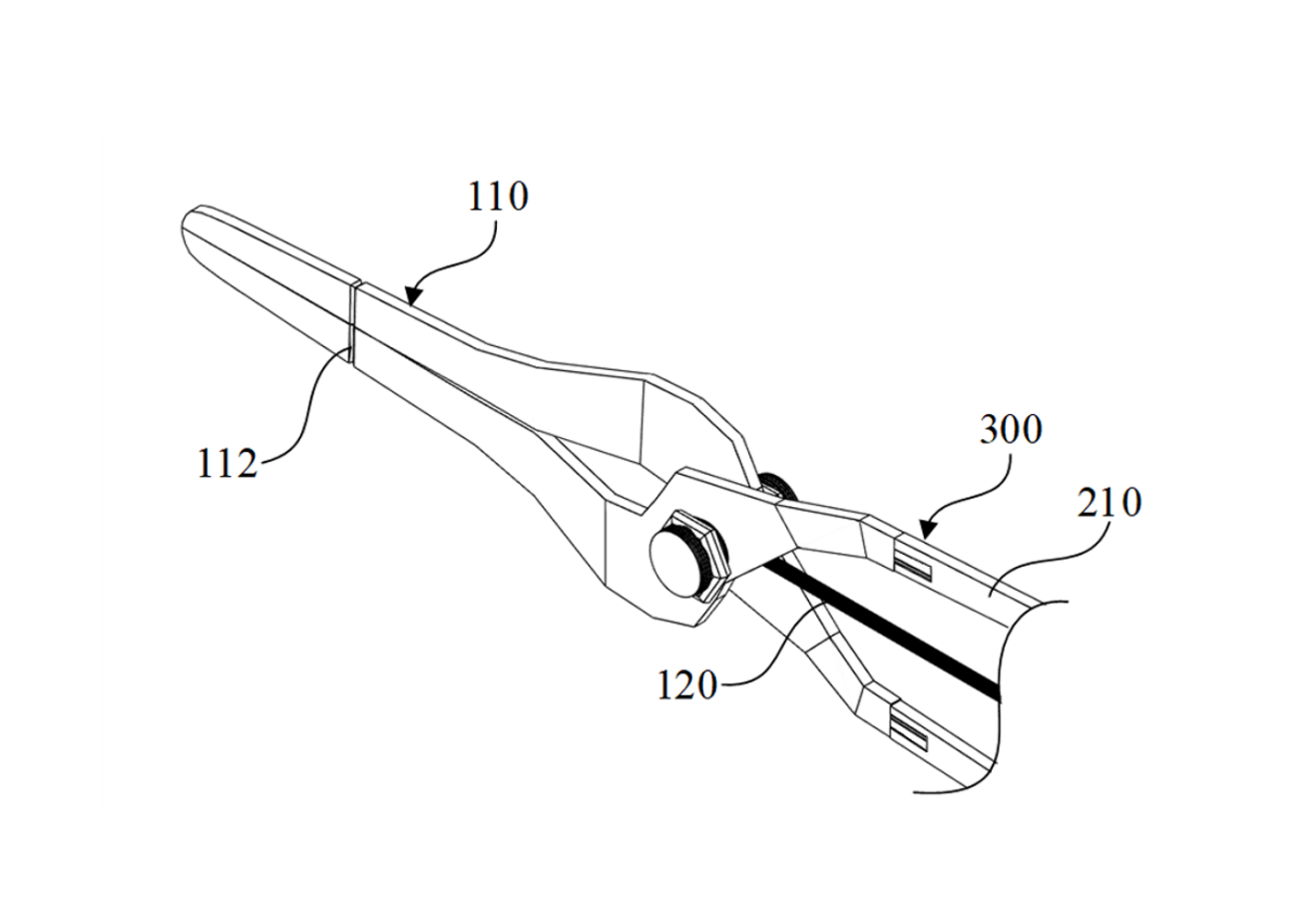
Patent FIG. 1 — overall instrument layout
The beak holds the surgical needle while the rotational rod transfers motion from the main gear to the jaw assembly.
Overview
What it is
The surgical needle holder combines a familiar two-ring shank with an added rotational mechanism. A sliding finger platform drives an assisting gear; that gear rotates the main rotational gear, which turns the rotational rod and rotates the beak holding the needle.
The design is intended for narrow or deep operative areas where large wrist movements are difficult or undesirable. By allowing the beak to rotate independently, the needle can follow a smoother suturing path with less tissue tearing and less hand strain.
Detailed Patent Design
Precise component breakdown
Primary mechanism
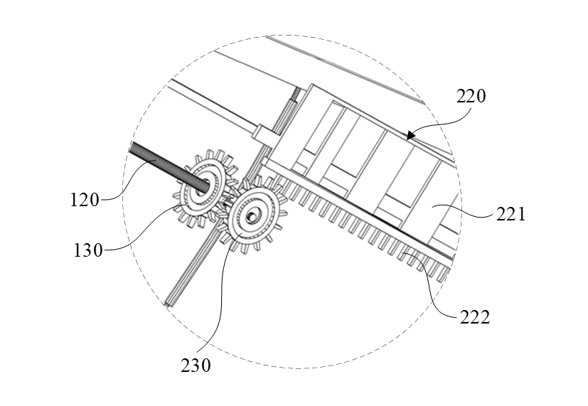
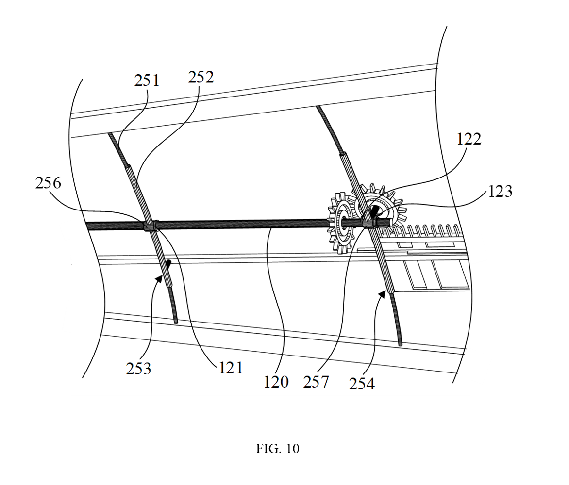
The central mechanical conversion is a compact rack-and-gear chain. The finger platform moves linearly along the railway, the gear-shaped margin drives the assisting gear, and the assisting gear rotates the main gear mounted coaxially to the rotational rod.
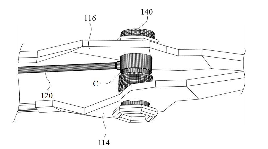
120Rotational rod transferring torque toward the anterior beak.
130Main rotational gear fixed to the rod.
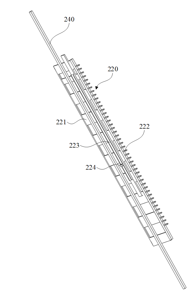
230Assisting gear meshing between the finger rack and main gear.
220Sliding finger platform used by the middle finger.
Jaw & beak assembly
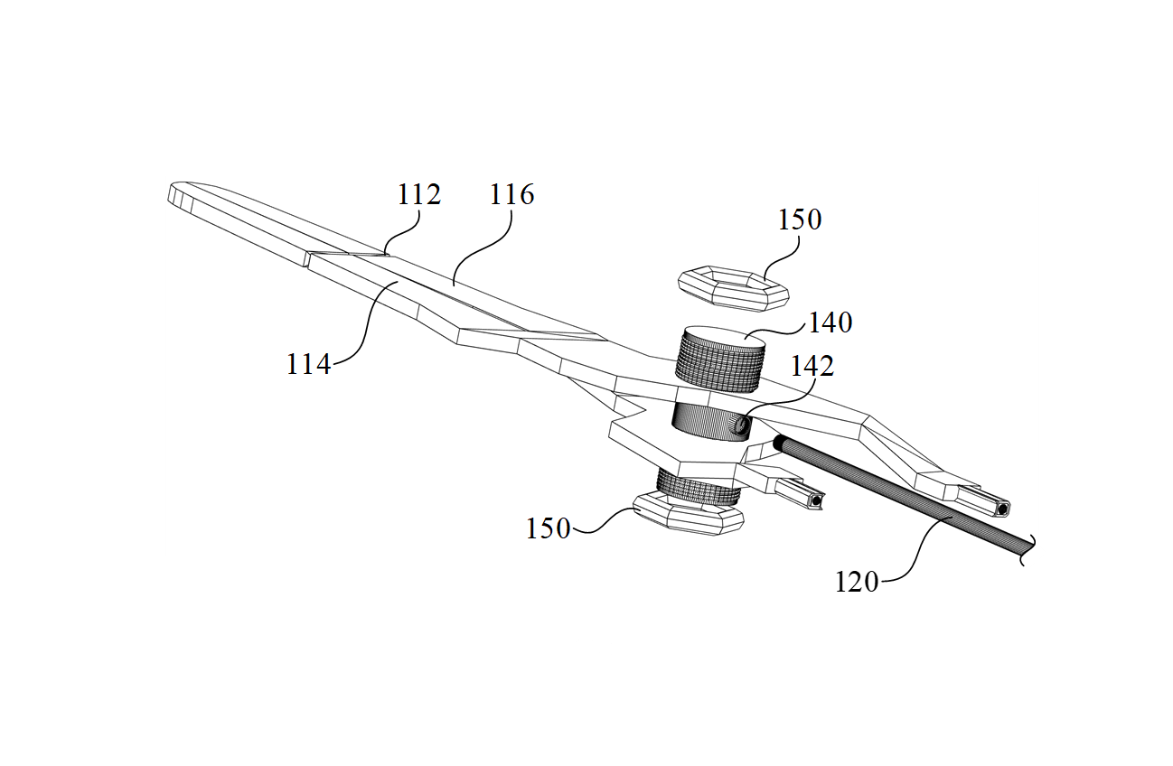
The anterior part uses a multi-functional holder to keep the first and second beak parts aligned while the rod rotates the entire jaw assembly. The beak includes a groove for holding the suture material and can be configured with a textured contact surface for added grip.
110Beak configured to hold a surgical needle.
114/116First and second beak parts forming the clamping jaw.
140Multi-functional holder creating the rotational axis.
150Screw nuts/caps holding the jaw assembly in place.
Patent Figures
Image-based subpage design
The subpage uses the patent drawings directly as the visual system so the page feels like an interactive technical exhibit rather than a generic project card.
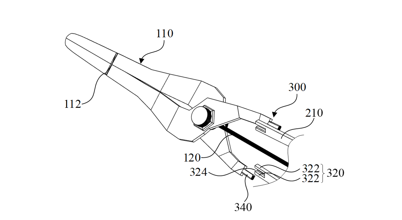
FIG. 3
Detached anterior-posterior junction and beak rotation clearance
FIG. 4
Attached beak and shank connection during normal opening/closing
FIG. 10
Curved telescopic railway supporters aligned with shank movement
FIG. 11
Finger platform mounted on railway with gear-shaped side margin
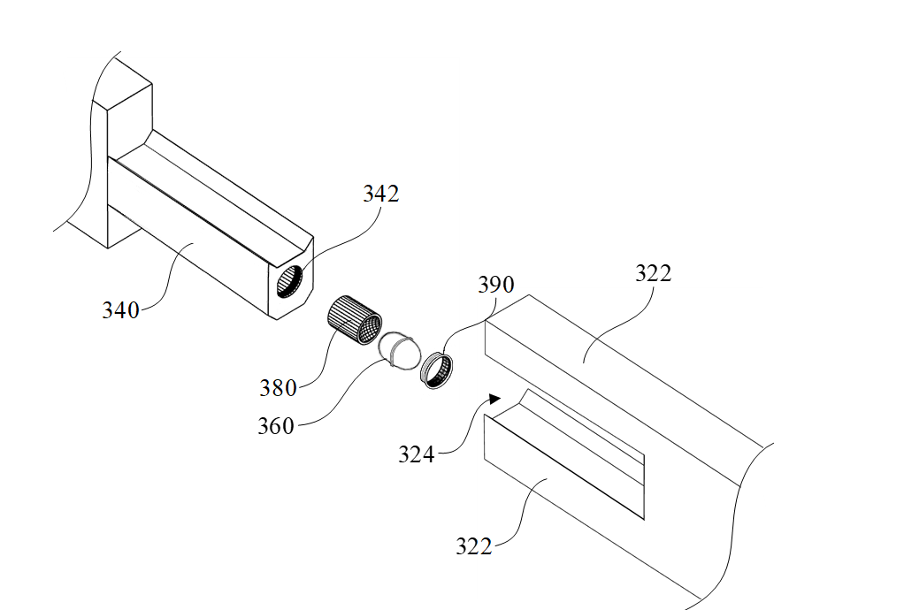
FIG. 13
Male/female junction, holder, ejector, and cover
FIG. 16
Beak holder detail locking the beak to the multi-functional holder
Operation
How the motion works
01 GripThumb and ring finger stay in the conventional rings.
02 SlideThe middle finger pushes or pulls the finger platform.
03 MeshThe rack teeth engage the assisting gear.
04 RotateThe assisting gear drives the main rotational gear and rod.
05 SutureThe beak rotates the needle through the tissue path.
Key Features
What sets it apart
Feature 01
Finger-driven rotational beak for confined suturing
Feature 02
Rack, assisting gear, main gear, and rod torque path
Feature 03
Detachable anterior-posterior junction for rotating motion
Feature 04
Curved telescopic railway supporters following shank opening